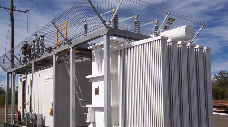
Vector Set of Transformers
Ⅰ. What is a transformer vector group?
The phase difference between a transformer's primary and secondary is represented by the transformer vector group. It also controls how a three-phase transformer's high-voltage and low-voltage windings are connected.
Ⅱ. Types of transformer vector groups
What is vector group of transformer? The vector group is a mechanism used by the International Electrotechnical Commission (IEC) to classify the arrangement of a three-phase transformer's high-voltage (HV) and low-voltage (LV) windings. The vector group's name refers to the winding configuration and the phase angle difference between them. Example: "Yd11" stands for star HV windings with 30 degree leads and triangle LV windings. Three-phase transformers can be linked in a number of different ways. The vector group of the transformer is determined based on the connections. The phase difference between the matching line voltages on the high-voltage and low-voltage sides divides three-phase transformers into four categories. The phase difference is the angle at which the low-voltage line voltage lags behind the high-voltage line voltage, and it is measured in 30° increments clockwise.
Ⅲ. The importance of vector groups in three-phase transformers
When connecting numerous transformers in parallel, this is one of the most critical considerations. For such transformers, different combinations of transformer wings create different phase angles and, as a result, varying voltage levels. When two separate transformer vector groups are connected, the phase difference of each transformer increases. Between the two transformers, a huge circulating current can flow, which is exceedingly dangerous. The significance of vector group in 3 phase transformers is that when they must be operated in parallel, the information on the transformer vector groups is critical.
Ⅳ. Groups of transformer calculation vectors
Transformer windings can be connected internally in a variety of ways. As a result, many types of connections have been standardized based on phase displacement. For the high-voltage and low-voltage windings, there are four vector groups, each with three types of connections. The phase changes between the EMFs of the high-voltage and low-voltage windings are denoted by the symbols 0, 6, 1 and 11 and are expressed in clock hours. For example, the clock hour 0 denotes a phase shift of zero degrees between the primary and secondary EMFs. Hour 6 denotes a 180 0 phase shifts, while 1 denotes a -300 phase shifts and 11 denotes a +300 phase shifts. The symbols Yy0, Dd1, and so on are stamped on the nameplate of the three-phase transformer's vector group. Here, Yy0 shows that the windings are entirely star-connected and that the phase shift between the primary and secondary electric potentials is zero degrees. Dy1 belongs to group 3 and its primary winding is connected in a triangle, while its secondary winding is connected in a star with a phase shift of -300.
Ⅴ. Vector group selection for the transformer
The transformer vector group is reliant on it.
1. Harmonics are eliminated: The Dy connection—y winding eliminates the 3rd harmonic and prevents it from resonating on the triangle side.
2. Parallel operation: The vector group and winding polarity of all transformers should be the same.
3. Earth fault relay: Dd transformers do not have a neutral, hence they require an earth fault relay. We can utilize sawtooth wound transformers with earth fault relays to create the neutral in such systems to limit earth faults.
4. Non-linear load types: for systems with various forms of harmonics and non-linear load types, such as boiler heaters, VFDS, and so on, we can utilize Dyn11, Dyn21, and Dyn31 configurations, in which the 30 degree voltage offset makes the supply system's third harmonic zero.
5. Different types of transformer connections: generator side triangle transformer connection, load side star transformer connection are the most common. Some may prefer the star transformer connection for power outlet import transformers, i.e. in transmission applications, as it eliminates the requirement for an earthed transformer on the generator side and potentially saves neutral insulation. This is how the majority of systems are set up. The Yd or Dy connection is the industry standard for all generator connections.
6. A number of parameters related to the transformer connection may be valuable in system design, and the application of these factors determines the optimal transformer option.
Jump to Content Sections
Leave a Message
You May Also Like
 English
  français
  Español
  русский
  العربية
  tiếng việt
  Malay
Malay  Indonesia
  বাঙালি

