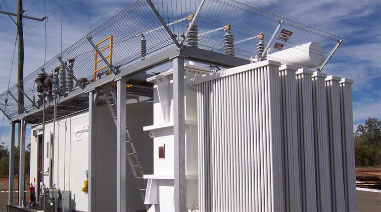
A Brief Introduction of the Combined Transformer
Transformers generally adopt protection methods: abnormal working conditions of transformers are mainly caused by overload, overcurrent caused by an external short circuit, neutral point overvoltage caused by a shallow ground short circuit, oil level reduction caused by oil tank leakage or cooling system failure. Temperature rise, etc. In addition, large-capacity transformers, due to their higher-rated working magnetic flux density, whose working magnetic density is proportional to the voltage frequency, may cause overexcitation faults of the transformer when operating at overvoltage or low frequency.
Ⅰ. Introduction of the combined transformer
The combined transformer was first developed by the relevant electrical companies in the United States. The fuses, multi-station ring network load switch, and off-excitation tap changer of this combined transformer are all installed in the transformer tank as its components. It is easy to change the operating condition of the transformer by replacing the fuses or operating the load switch outside the tank. The high voltage side is supplied with electrical energy by elbow cable, which is pluggable with the load. A low-voltage outlet bin is installed outside the fuel tank. There is space in the bin to install protection devices and measuring instruments as required. All live parts of the combined transformer are in the box with no exposed live parts. Because the main components are all in the fuel tank, we call it a combined transformer.
Ⅱ. The internal structure of the combined transformer
Like the high-voltage switchgear substation or box-type substation, the high-voltage wiring scheme of the combined transformer is also divided into ring network type and terminal type. The ring network type is represented by the letter H. In contrast, the terminal type is represented by the letter Z. Generally, the power units use terminal-type wiring schemes. In comparison, those operated and maintained by power supply companies use ring-net-type wiring schemes so that the power grid can provide power supply flexibly and reliably. At this time, the cross-section of the high-voltage network cable of the main ring unit should be selected in combination with the load current of the distribution station and the ring network through current. For power consumers powered by dual power sources, the high-voltage wiring scheme of the combined transformer can also be a ring network type to avoid the system through current causing measurement confusion and the complexity of the relay protection setting. It may even cause uncertainty in the safe operation of the power grid.
The internal structure of the combined transformer is mainly a transformer. The high-voltage side of the transformer is equipped with a load switch, which can be directly connected to the grid to receive power. It is connected in series with a fuse for fault protection. The low-voltage side is connected to a switchboard to distribute the charge outwards. The structure of a combined transformer is simpler than that of a box-type substation, and it can only be regarded as a transformer for additional power distribution equipment.
Jump to Content Sections
Leave a Message
You May Also Like
 English
  français
  Español
  русский
  العربية
  tiếng việt
  Malay
Malay  Indonesia
  বাঙালি


