English
  français
  Español
  русский
  العربية
  tiếng việt
  Malay
Malay  Indonesia
  বাঙালি
33kV vs 11kV Transformer: Specifications, Nameplate Details and Applications
A medium-voltage transformer must be selected according to the network voltage, rated capacity, insulation requirements, cooling method, connection configuration, and expected load. Among commonly used distribution and power-system ratings, 11kV transformers serve different positions within electrical networks.
A 33/11kV transformer is particularly important where a higher-voltage subtransmission network needs to be reduced to an 11kV medium-voltage distribution level. Understanding 33kv transformer specifications, 11kv transformer details, winding arrangements, and nameplate information, can help engineers and buyers evaluate the right transformer for a project.
What Is a 33/11kV Transformer?
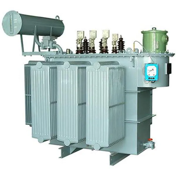
A 33/11kV transformer is a three-phase power transformer designed to transfer electrical energy between a 33kV high-voltage side and an 11kV medium-voltage side.
The equipment supplied for 33/11kV applications can be used in substations, power centers, industrial facilities, and distribution networks. The referenced product configuration includes oil-immersed construction, with ONAN and ONAF/OFAF cooling options, mineral oil as the cooling medium, and copper or aluminum windings. Its stated capacity range is 100kVA to 31,500kVA, while the primary-voltage range is 30kV to 38.5kV.
In a typical network, the transformer receives power at approximately 33kV and delivers it at approximately 11kV for subsequent distribution.
Difference Between 11kV and 33kV Transformers
The most important difference between 11kv and 33kv transformers is their voltage class and their position within the power network.
A 33 kv distribution transformer or power transformer is designed for a higher-voltage network and generally requires higher insulation levels and greater electrical clearances. An 11 kv transformer operates at a lower voltage and is commonly positioned closer to distribution loads.
Parameter | 33kV Transformer | 11kV Transformer |
Typical voltage class | 33kV | 11kV |
Network position | Subtransmission / primary distribution | Medium-voltage distribution |
Insulation requirement | Higher | Lower than 33kV class |
Typical application | Substations and network interconnection | Distribution substations and industrial loads |
Common configuration | 33/11kV | 11kV/LV |
Typical downstream voltage | 11kV | 400V/415V or other LV level |
Design priority | Network transfer and voltage transformation | Local distribution and load supply |
The actual system voltage and transformer rating must always be confirmed against the utility's specifications rather than inferred solely from the nominal voltage.
33kV Transformer Specifications to Check
When evaluating 33kv transformer specifications, buyers should look beyond the nominal voltage. Important parameters include rated capacity, voltage ratio, vector group, impedance voltage, cooling method, winding material, insulation level, tap changer, and oil-preservation system.
For example, the referenced 33/11kV series specifies three-phase construction, 50 or 60Hz frequency, ONAN and ONAF/OFAF cooling, multiple vector-group options, and capacities from 100kVA to 31,500kVA. It also lists off-circuit or on-load tap-changer options.
Rated Capacity
Transformer capacity is normally expressed in kVA or MVA rather than simply by voltage. A 33 kva transformer, for example, is a very different specification from a 33kV transformer.
Therefore, 33kva transformer is not interchangeable terms.
Voltage Ratio
For a 33/11kV unit, the nominal voltage ratio is approximately 3:1. The actual rated primary voltage may include a specified range or tap positions to accommodate system-voltage requirements.
Vector Group
Vector group defines the phase displacement and winding connection relationship between the high- and low-voltage windings.
The referenced 33/11kV product supports configurations including Dyn11, Yd11, and Ynd11.
The correct vector group is important when transformers operate in parallel or connect to an existing network.
33 11kV Transformer Nameplate Details
Understanding 33 11kv transformer nameplate details is essential during installation, commissioning, maintenance, and replacement.
A transformer nameplate normally provides the key information required to identify the electrical and mechanical characteristics of the unit.
Typical information includes:
Nameplate Item | What It Indicates |
Manufacturer | Transformer manufacturer and identification |
Serial number | Individual equipment identification |
Rated power | kVA or MVA capacity |
HV rated voltage | High-voltage winding rating |
LV rated voltage | Low-voltage winding rating |
Frequency | Usually 50Hz or 60Hz |
Phase | Single-phase or three-phase |
Vector group | Winding connection and phase displacement |
Impedance voltage | Percentage impedance |
Cooling method | Such as ONAN or ONAF |
Insulation information | Applicable insulation and dielectric ratings |
Tap range | Available voltage adjustment |
Total/individual losses | Transformer efficiency characteristics |
The IEC general transformer standard also addresses rating information and technical requirements. The IEC 60076-1:2011 – Power Transformers – Part 1: General applies to three-phase and single-phase power transformers and includes requirements concerning specification, safety, environmental considerations, testing, and condition monitoring.
The actual nameplate should always be treated as the authoritative source for a particular transformer.
33kV Transformer Diagram: How the Voltage Path Works
A simplified 33kv transformer diagram can be understood as:
33kV Network → HV Winding → Magnetic Core → LV Winding → 11kV Network
The high-voltage winding receives energy from the 33kV network. Alternating magnetic flux generated in the core induces voltage in the low-voltage winding. The resulting 11kV output can then feed medium-voltage feeders.
The transformer itself does not need a direct electrical connection between the primary and secondary windings in a conventional two-winding configuration. Energy is transferred electromagnetically through the magnetic circuit.
A typical substation arrangement may therefore look like:
33kV Incoming Line → HV Switchgear → 33/11kV Transformer → 11kV Switchgear → Distribution Feeders
This arrangement allows protection and switching equipment to isolate the transformer and control different sections of the network.
11kV Transformer Winding and Connection
The 11kv transformer winding is a critical part of the transformer's electrical design. Its conductor size, insulation system, arrangement, and connection determine how electrical energy is transferred between voltage levels.
For a 33/11kV transformer, the high-voltage winding is designed for the 33kV side, while the low-voltage winding is designed for the 11kV side.
Winding material can be copper or aluminum. The referenced product specification identifies both as available winding materials.
The winding system must also withstand thermal and mechanical stresses caused by normal loading and short-circuit events. The IEC 60076-5:2006 – Power Transformers – Part 5: Ability to Withstand Short Circuit establishes requirements for transformers to withstand the thermal and dynamic effects associated with external short circuits.
11kV Distribution Transformer Applications
An 11kv distribution transformer is generally used closer to consumers than a 33kV network transformer.
Typical applications include:
Industrial distribution systems
Commercial complexes
Utility distribution substations
Infrastructure projects
Manufacturing facilities
Mining and processing facilities
Local medium-voltage feeders
An 11kv step down transformer may then reduce 11kV to a low-voltage supply suitable for end-use equipment, such as 400V or 415V systems, depending on regional electrical standards.
This creates a multi-stage network in which voltage is progressively reduced as electricity moves from transmission or subtransmission infrastructure toward consumers.
33kV Power Transformer Applications
A 33kv power transformer is generally positioned at a higher level of the distribution network.
Typical applications include:
Substations
A 33kV transformer can reduce voltage from a 33kV network to 11kV feeders. This makes it suitable for primary distribution substations.
Industrial Complexes
Large industrial facilities may receive electricity at medium or high voltage and use transformers to establish appropriate internal distribution levels.
Public Distribution Networks
33kV networks can transfer electricity across larger service areas before transformers reduce the voltage for local feeders.
The referenced 33/11kV transformer is described for power centers, substations, networks, commercial buildings, industrial complexes, and public distribution systems.
Cooling and Thermal Performance
Cooling is another important part of 11kv transformer details and 33kV transformer design.
The referenced 33/11kV transformer supports ONAN, ONAF, and OFAF cooling arrangements.
The selection of cooling equipment depends on transformer capacity, load profile, ambient conditions, and required thermal performance.
The IEC 60076-2:2011 – Power Transformers – Part 2: Temperature Rise for Liquid-Immersed Transformers identifies transformer cooling methods, temperature-rise limits, and temperature-rise test methods for liquid-immersed transformers.
Proper thermal design is essential because excessive temperature can accelerate insulation ageing and reduce expected service life.
Insulation and Protection Requirements
As voltage increases from 11kV to 33kV, insulation coordination becomes increasingly important. Transformer bushings, windings, clearances, and dielectric systems must be selected according to the applicable voltage class.
The IEC 60076-3:2013+A1:2018 – Power Transformers – Part 3: Insulation Levels, Dielectric Tests and External Clearances in Air specifies insulation requirements and corresponding dielectric tests for power transformer windings and terminals.
Protection equipment should also be coordinated with the transformer rating, impedance, fault level, and network configuration.
How to Select an 11kV or 33kV Transformer
Before purchasing an 11kv transformers or 33kV unit, confirm the following:
1. Primary and secondary voltage.
2. Required kVA or MVA capacity.
3. Frequency and phase configuration.
4. Vector group.
5. Impedance voltage.
6. Cooling method.
7. Tap-changer requirements.
8. Winding material.
9. Installation altitude and ambient temperature.
10. Applicable standards and utility requirements.
For larger installations, short-circuit withstand capability, insulation coordination, losses, sound level, transport conditions, and maintenance access should also be evaluated.
FAQ
What is the difference between 11kV and 33kV?
11kV and 33kV represent different voltage levels. A 33kV system operates at a higher nominal voltage and is generally used farther upstream in a distribution or subtransmission network, while 11kV is commonly used for medium-voltage distribution closer to loads.
What are the main 33kv transformer specifications?
Important specifications include rated capacity, HV and LV voltage, vector group, impedance voltage, cooling method, frequency, winding material, tap range, insulation level, and losses.
What are 33 11kv transformer nameplate details?
Typical nameplate details include rated power, voltage ratings, frequency, phase, vector group, impedance, cooling class, serial number, manufacturer, and tap information.
Is a 33kVA transformer the same as a 33kV transformer?
No. 33kVA refers to apparent power capacity, whereas 33kV refers to voltage. A transformer can have a 33kV voltage rating and a capacity measured in hundreds or thousands of kVA.
What is an 11kV step down transformer?
It is a transformer designed to reduce an 11kV supply to a lower voltage suitable for local distribution or end-use equipment.
What is the difference between an 11kV transformer and a 33kV transformer?
The primary difference is the voltage class. A 33kV transformer requires insulation and electrical clearances appropriate to its higher voltage level, while an 11kV transformer is designed for the lower voltage class.
Conclusion
A 33/11kV transformer provides an important link between higher-voltage distribution or subtransmission networks and 11kV medium-voltage feeders. When evaluating a 33kv transformer, engineers should consider much more than nominal voltage. Capacity, vector group, impedance, winding design, cooling, insulation, tap-changing capability, losses, and protection requirements all affect the suitability of the equipment.
Likewise, understanding 11kv transformer details helps users distinguish voltage ratings from capacity ratings and select equipment according to its actual network position.
For transformer procurement and engineering design, the nameplate, manufacturer's technical documentation, project specifications, and applicable standards should always be checked together.
Jump to Content Sections
Leave a Message
You May Also Like